Engineering-Grade
Systems Design
Platform
A unified platform for broadcast and media infrastructure planning. Define equipment, calculate costs, build floor plans, create schematics, and generate professional drawing packs — all in one structured workflow.
 Detail Schematic
What BroadcastSys
Actually Produces
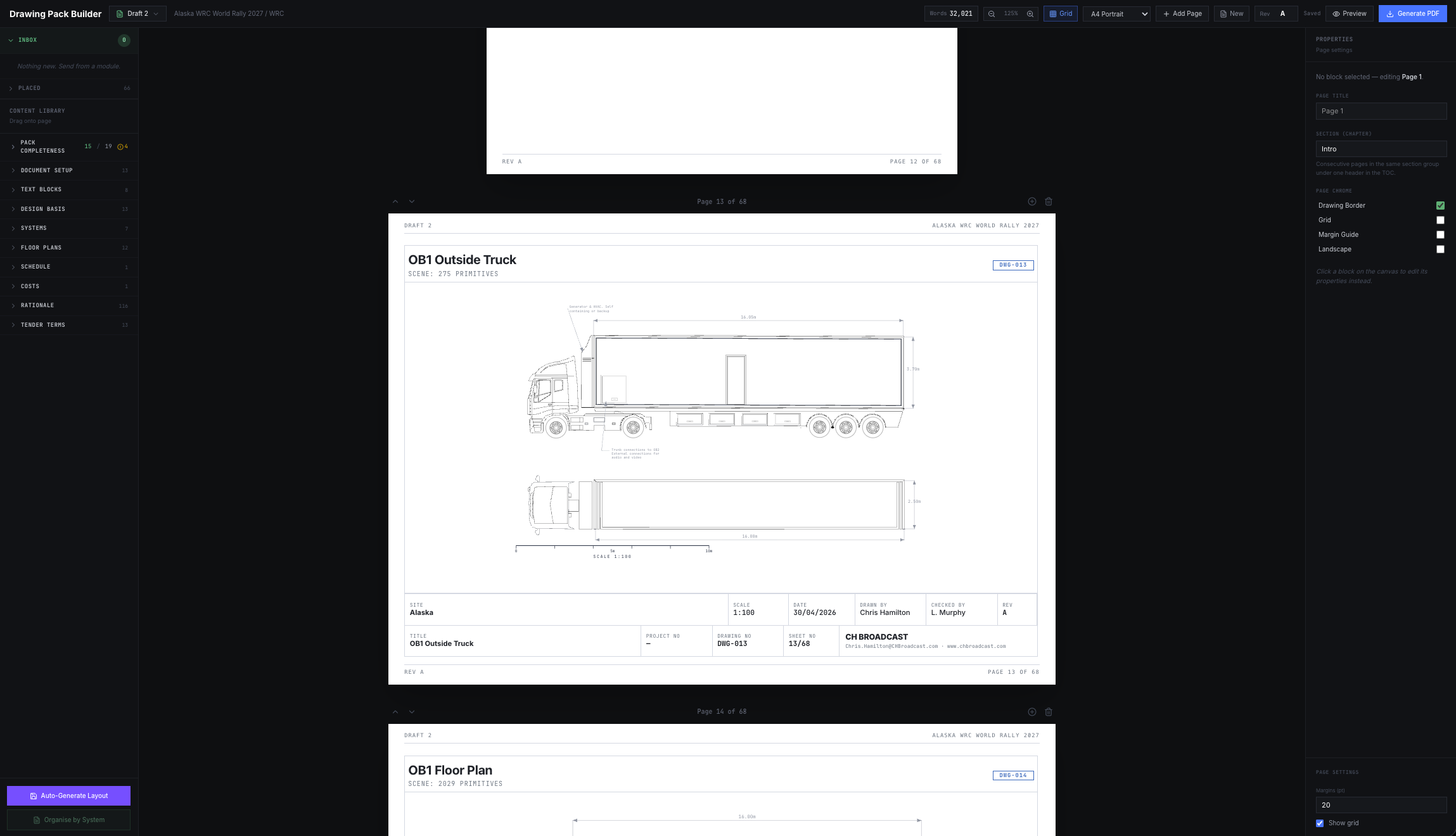
These are real deliverables from a recent OB-truck tender — not mockups, not previews. Zoom in to see the depth: cable-level schematic detail, dimensioned floor plans, and a multi-page A3 pack with the engineering rationale on every line.
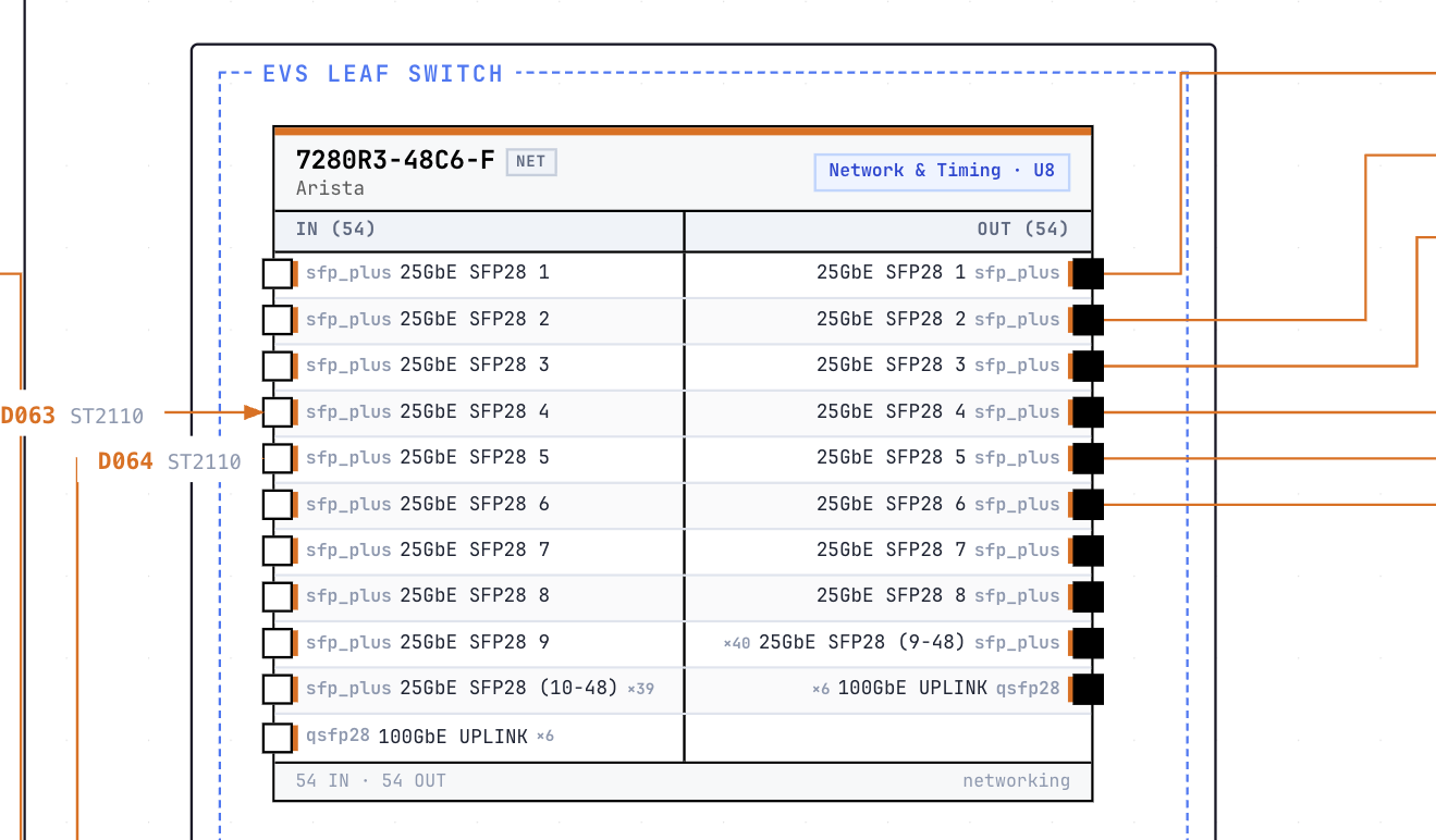
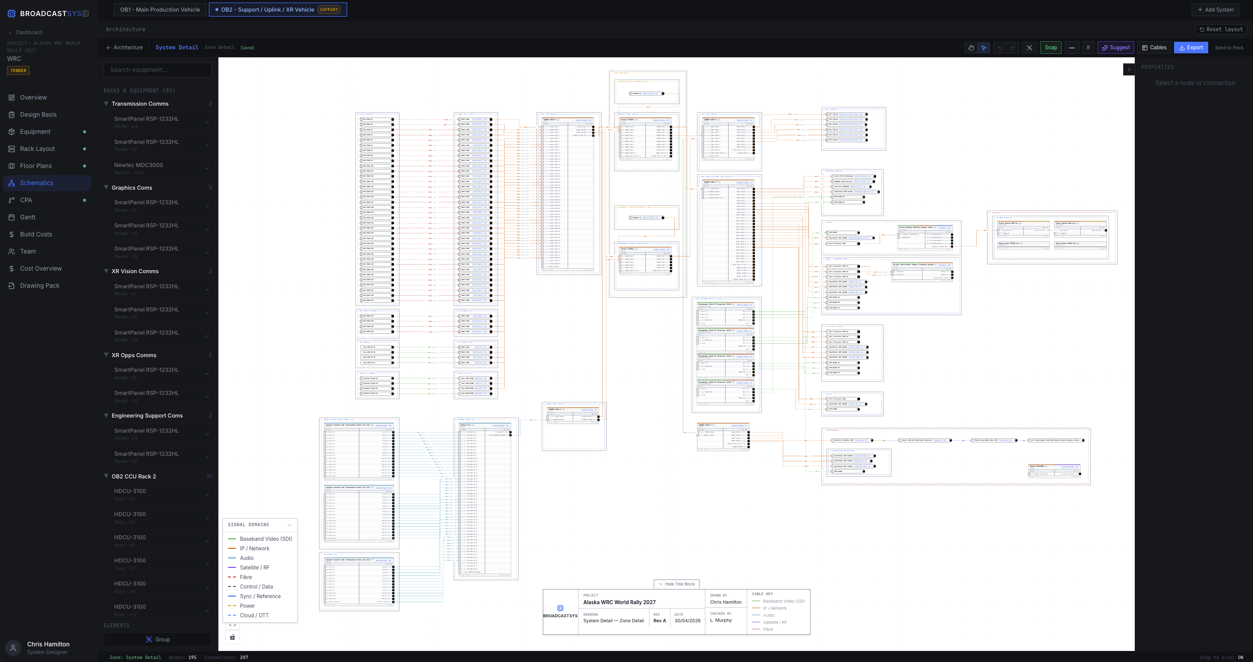 Vector · Cable-level zoom
Detail Schematic
Every port, every cable, every connector. Vector-preserved end-to-end so the client can zoom in the printed pack and verify routing port by port.
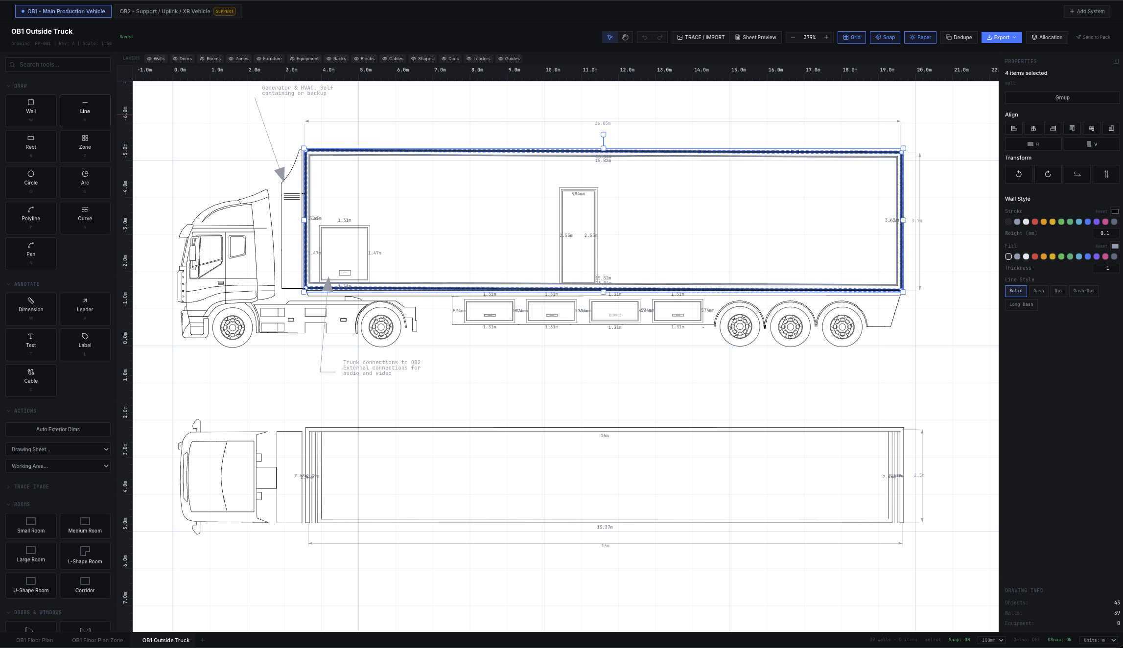 CAD-grade · Dimensions to mm
Floor Plan
Wall geometry, equipment placement, dimensions, doors, and zone boundaries. DXF import for existing CAD; pen tool and dimension chains for new builds.
 A3 · Multi-system · Vector PDF
Tender Drawing Pack
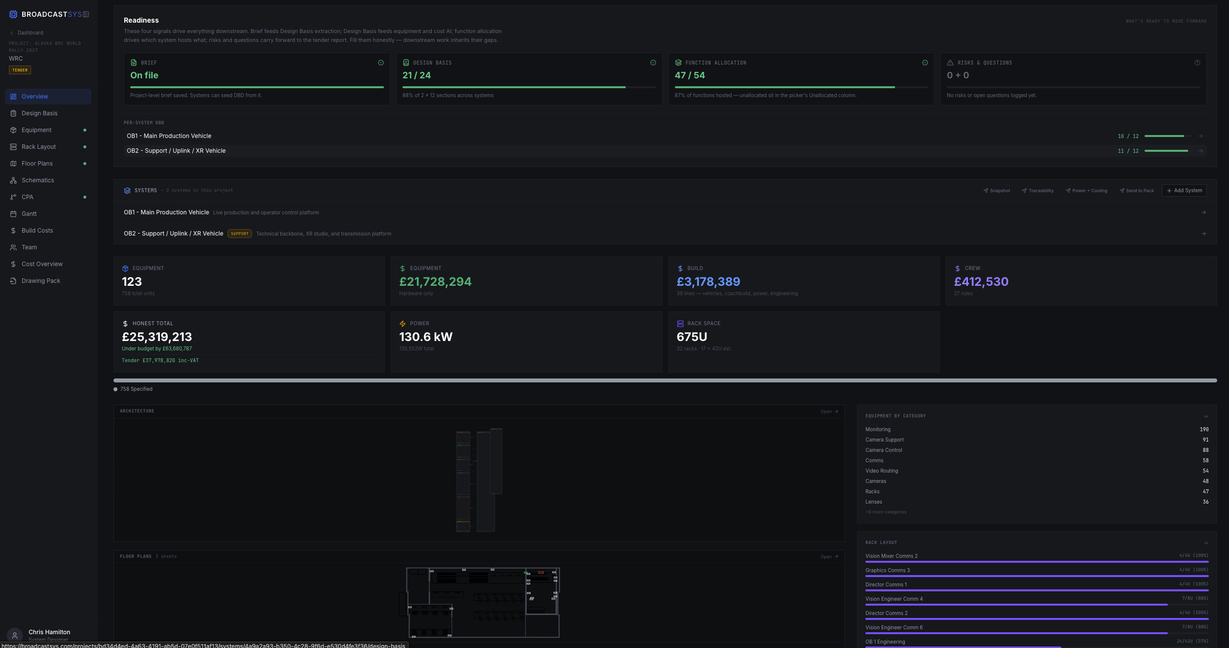
Project snapshot, design basis, methodology, traceability matrix, schematics, costs, programme — one signed deliverable, generated from the same authored model.
Sample pack · Client and project identifiers anonymised
Systems Design Information
is Fragmented
Equipment lists in spreadsheets. Floor plans in CAD. Schematics in Visio. Costs calculated separately. Project timelines disconnected. Documentation scattered across tools.
Disconnected Data
Equipment specs, costs, and layouts exist in separate files with no connection between them.
Manual Updates
Change one piece of equipment and you must manually update drawings, schedules, and cost sheets.
Inconsistent Documentation
Drawing packs assembled manually from different sources with varying formats and standards.
The Solution: Connected Workflow
BroadcastSys brings equipment, costs, layouts, schematics, and planning into one platform. Define your equipment once, and it flows through floor plans, schematics, schedules, and exports automatically. No manual syncing. No disconnected files.
Complete Systems Design Workflow
From initial equipment specification to final drawing pack export, every stage is connected in a single platform.
Project Setup
Create project, define scope, set client details and project parameters.
Equipment & Specs
Define all equipment with specifications, inputs, outputs, and technical details.
Cost Calculation
Calculate project costs with equipment, labour, and contingency budgets.
Floor Plans
Build architectural layouts with walls, rooms, and equipment placement.
Schematics
Create signal flow diagrams with equipment connections and cable types.
Critical Path
Build task dependencies and identify critical implementation paths.
Gantt Timeline
Visualize project schedule with task durations and dependencies.
Export Pack
Generate professional A3 drawing packs with all documentation.
Integrated Design Tools
Seven specialized modules working together to create a complete systems design environment.
Equipment & Specifications
Define equipment with full technical specifications, inputs, outputs, dimensions, and power requirements. Build a reusable equipment library.
Cost Planning
Calculate equipment costs, labour, and contingency. Automatically update totals when equipment changes. Export cost summaries.
Floor Plan Editor
CAD-style floor plan builder with walls, doors, windows, and equipment placement. Grid-based precision with snap-to-grid alignment.
Schematic Designer
Node-based schematic editor for signal flow diagrams. Connect equipment ports with labeled cables. Orthogonal routing.
Critical Path Analysis
Visual workflow diagram for task dependencies. Build implementation paths and identify critical sequences automatically.
Gantt Timeline
Timeline visualization of project schedule. Synced with CPA tasks. Adjust durations and dependencies visually.
Drawing Pack Export
Generate professional A3 drawing packs with title blocks, borders, and legends. Export floor plans, schematics, schedules, and cost reports as a complete documentation set. Customizable title blocks and sheet formatting.
See the Interface
Clean, technical interfaces designed for precision and efficiency.
Engineering-Grade
Drawing Packs
Generate complete documentation sets with professional A3 drawings, title blocks, borders, and legends. Export floor plans, schematics, equipment lists, cost reports, and project schedules as print-ready PDF documents.
Vector-Preserved Schematics
Detail schematics print as vector PDF — clients zoom in to verify cabling at port level. No pixelation, no rasterisation.
Multi-System Packs
One project produces N system designs (OB1 + OB2, Studio + OB) into a single signed pack with per-system schematics, racks, and costs.
Engineered Defence on Every Line
Traceability matrix, design-basis context, and rationale fields surface the why behind every spec, not just the what.
Sample tender pack · Anonymised
Build Your Next System
in One Platform
From equipment specification to final drawing pack, manage the entire systems design workflow in a single technical environment.